Shift Harness and GCU
The shift harness collects signals from the steering wheel and operates the pneumatic sytem to shift the car.
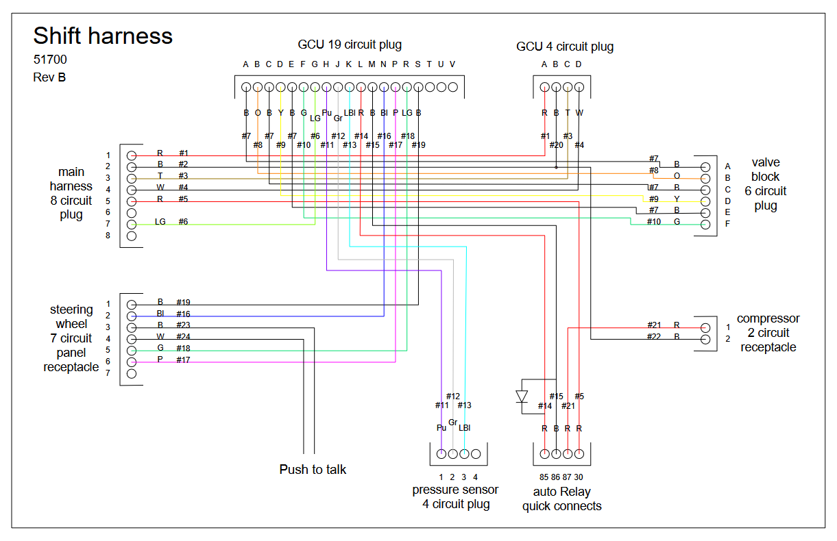
Shift harness diagram for mechanical throttle car
Please click to open the interactive diagram.
Open the shift-harness-wiring-diagram diagram in a new tab
The shift system is powered by two fused circuits from the main harness: the signal fuse circuit (ignition-switched, powers the GCU) and the compressor fuse circuit (always hot via the ABS fuse, powers the compressor). The interactive diagram above shows all wire routing, pin assignments, and Gen1/Gen2 differences. The easiest way to tell which generation engine is in a car is to check the pedal box for a throttle cable (Gen1, mechanical throttle) or accelerator pedal sensor (Gen2, drive-by-wire).
GCU Pinout
Section titled “GCU Pinout”Wiring Diagram
Section titled “Wiring Diagram”The following is a wiring diagram for the GCU on the Gen1 (throttle cable) cars. For Gen2, blip and throttle cut are handled by QuickShift on the ECU, which means that mosfets 3 and 4 are not used, and an additional wire is sent to pin 12 on the board for the gearshift sensor mimic. More details are below.
Please click to open the interactive diagram.
Open the gcu-wiring-diagram diagram in a new tab
Detailed Pin Table
Section titled “Detailed Pin Table”For debugging purposes, we provide the following pin table for the GCU:
Input Pins
Section titled “Input Pins”| Pin Name | Number | Notes | Pin Name | Direction | Pullup/Pulldown |
|---|---|---|---|---|---|
| Upshift paddle switch | 18 | Filtered through pin 10. | PIN_UP | INPUT | PULLUP |
| Downshift paddle switch | 19 | Filtered through pin 9. | PIN_DOWN | INPUT | PULLUP |
| Neutral paddle switch | 3 or 20* | Pin 20 on KLine cars, 3 on DBW. Filtered through pin 8. | PIN_NT | INPUT | PULLUP |
| Tank air pressure sensor (analog) | A6 | Default 70-90psi hysteresis. | PIN_TANK_PRESSURE | INPUT | PULLUP |
Explanation and Debugging
Section titled “Explanation and Debugging”For symptom-first troubleshooting (paddle direction dead, asymmetric shifts, compressor issues, reading the serial console, etc.), see GCU Debugging. The rest of this section covers pin-level electrical reference.
Paddle Switches (Upshift, Downshift, Neutral)
The paddle switches are all configured as INPUT_PULLUP, meaning the GCU holds each pin HIGH (~5V) through an internal pull-up resistor. When you press a paddle, the switch connects the pin to ground, pulling it LOW (0V). The GCU reads this LOW signal as a shift command.
To debug paddle inputs with a multimeter:
- Set your multimeter to DC voltage.
- Probe the relevant pin on the GCU connector (pin 18 for upshift, pin 19 for downshift, pin 3 or 20 for neutral) against ground (pin 2 of the main harness connector).
- With the paddle not pressed, you should read approximately 5V (the pull-up holding the line high).
- With the paddle pressed, you should read approximately 0V (the switch connecting to ground).
If you read 0V at all times, the switch may be stuck closed, or there is a short to ground in the wiring. If you read 5V at all times even when pressing the paddle, the switch is not making contact, there is an open circuit in the wiring, or the coil cable connection has a bad pin.
The upshift and downshift paddle signals pass through a capacitor filter on the intermediate board (pins 10 and 9, respectively) before reaching the logic board (pins 18 and 19). If you suspect the filter capacitor is the problem, you can bypass it by jumping pin 10 to pin 18 (upshift) or pin 9 to pin 19 (downshift) to test.
Air Pressure Sensor
The tank air pressure sensor is an analog input on pin A6, also configured with INPUT_PULLUP. It is a 10-bit sensor (range 0–1023) that reads 0.1633 psi per unit. The GCU uses a hysteresis window of 70–90 psi: it turns the compressor on when tank pressure drops below 70 psi and off when it reaches 90 psi.
The INPUT_PULLUP configuration means the GCU’s internal pull-up resistor holds pin A6 at ~5V. The pressure sensor acts as a variable resistance to ground, forming a voltage divider — as pressure changes, the voltage at A6 changes proportionally. This also provides a fail-safe: if the sensor wire is disconnected or broken, the pull-up pulls A6 to 5V, which the GCU reads as high pressure. The compressor stays off, which is the safe failure mode. A disconnected sensor reading low would run the compressor continuously against a potentially leaky or overpressured system.
To debug the pressure sensor:
- Set your multimeter to DC voltage and measure pin A6 against ground.
- The voltage should vary proportionally with tank pressure. At a full tank (~90 psi), expect a higher voltage reading; at an empty tank, expect a lower reading.
- If the reading is stuck at 0V or 5V regardless of tank pressure, the sensor may be faulty or disconnected.
If the compressor runs continuously, the pressure sensor may be reading low (bad sensor, air leak, or wiring issue). If the compressor never turns on, the sensor may be reading artificially high (or disconnected — see fail-safe above), or the issue may be on the output side (relay or compressor fuse circuit).
The pressure sensor connects to the shift harness via the 4-circuit pressure sensor plug. The sensor signal wire (#12) runs from this plug to the GCU 19-pin connector. Check for continuity along this path if sensor readings are suspect.
Compressor
The compressor is controlled by the GCU via a standard automotive relay in the shift harness. The GCU’s pin D11 drives an internal MOSFET (labeled “5 — compressor control” on the GCU board), which switches the ground side of the relay coil. When the GCU energizes the MOSFET, it completes the ground path through relay pin 86, energizing the coil (pin 85), and closing the relay contacts — connecting 12V from pin 30 to pin 87, which powers the compressor.
The compressor fuse circuit is always hot (directly connected to the battery via the ABS fuse), so the compressor should run whenever the relay is energized — regardless of ignition switch position. The GCU does need ignition power to read the pressure sensor and command the relay.
The signal path is:
- GCU reads low pressure on A6 → GCU sets D11 HIGH → MOSFET 5 switches on
- Relay coil energized (pin 85 to pin 86 through MOSFET ground) → relay clicks closed
- 12V from main harness pin 5 (ABS fuse) → relay pin 30 → relay pin 87 → compressor pin 1 (red wire, #21)
- Compressor pin 2 (black wire, #22) → ground
To debug the compressor:
- Check the fuse. Verify the ABS fuse in the fuse box is intact. This supplies 12V to the compressor circuit via pin 5 of the main harness connector, which reaches relay pin 30.
- Listen for the relay. With the ignition on and tank pressure below 70 psi, listen for the relay clicking. If you don’t hear a click, either the GCU is not sending the signal or the relay coil circuit is open.
- Test the compressor directly. Disconnect the compressor 2-circuit receptacle and apply 12V directly to pin 1 (red) and ground to pin 2 (black). The compressor should run. If it doesn’t, the compressor itself is faulty.
- Test the relay directly. The relay uses standard automotive quick-connect terminals (85, 86, 87, 30). Disconnect it from the harness and apply 12V to pin 85 and ground to pin 86. You should hear a click, and you should have continuity between pins 30 and 87. If not, replace the relay.
- Test the GCU relay output. With the relay connected and tank pressure below 70 psi, check for voltage at relay pin 85 against ground. If the GCU is commanding the compressor on, the MOSFET should be pulling pin 86 to ground, completing the coil circuit. If no click occurs and the relay tested good in step 4, the GCU or its MOSFET may be faulty.
- Check for air leaks. If the compressor runs but the tank does not pressurize, or the compressor cycles on excessively, check for air leaks in the pneumatic lines and fittings. Spray soapy water on connections and look for bubbles.
Output Pins
Section titled “Output Pins”| Pin Name | Number | Notes | ||
|---|---|---|---|---|
| Air valve 1: upshift | 4 | Triggers air shifter | OUTPUT | None |
| Air valve 2: downshift | 5 | Triggers air shifter | OUTPUT | None |
| Air valve 3: blip | 6 | KLine only; pulls throttle cable | OUTPUT | None |
| Solid-state ignition coil interrupt | 7 | KLine only; interrupts ignition coils | OUTPUT | None |
| Compressor relay | 11 | Turns on air compressor | OUTPUT | None |
| Gearshift sensor mimic (PWM) | 12 | DBW only; emulates bike gear lever sensor to initiate blip/throttle cut | OUTPUT | None |
| Debug LED (red, blip) | 53 | Debug LED | OUTPUT | None |
| Debug LED (yellow, downshift) | 47 | Debug LED | OUTPUT | None |
| Debug LED (green, upshift) | 41 | Debug LED | OUTPUT | None |
📥 Download: GCU KLine Wiring Diagram.pdf
Debugging
Section titled “Debugging”To pull data from the GCU, use a USB-B cable (like you see on a printer). We like these adapters.
You can read the internal logs using the attached zip.
Reading the LEDs goes as follows:
- Green is upshift
- Red is downshift
- Green + yellow is neutral upshift; red + yellow is neutral downshift.
- When the compressor is running, the yellow LED will flash on versions ≥ 3.0.6.
Manual Pneumatic Shift Test
Section titled “Manual Pneumatic Shift Test”If the GCU is suspect or you want to bench the pneumatic system independent of the electronics, you can shift the gearbox manually by moving the pneumatic shift arm forward and backward at the valve block. This bypasses the GCU and exercises the air path + cylinder + linkage end-to-end. A symmetric movement that produces a clean shift in both directions means the pneumatic side is healthy and the fault sits in the GCU, paddle, or wiring.
Shifter Cylinder Alignment
Section titled “Shifter Cylinder Alignment”If shifts in one direction (up or down) miss more often than the other, the connection between the pneumatic shift cylinder and the shift lever may be misaligned. The cylinder needs equal range of motion in both directions; if it doesn’t, the weak direction stalls before the dogs engage.
To realign: loosen the red-circled bolt below and adjust until the cylinder swings the same distance fore and aft. The shifter bolt (at the 2” mark) to the case bolt on the left with the red mark should measure 1.25”.
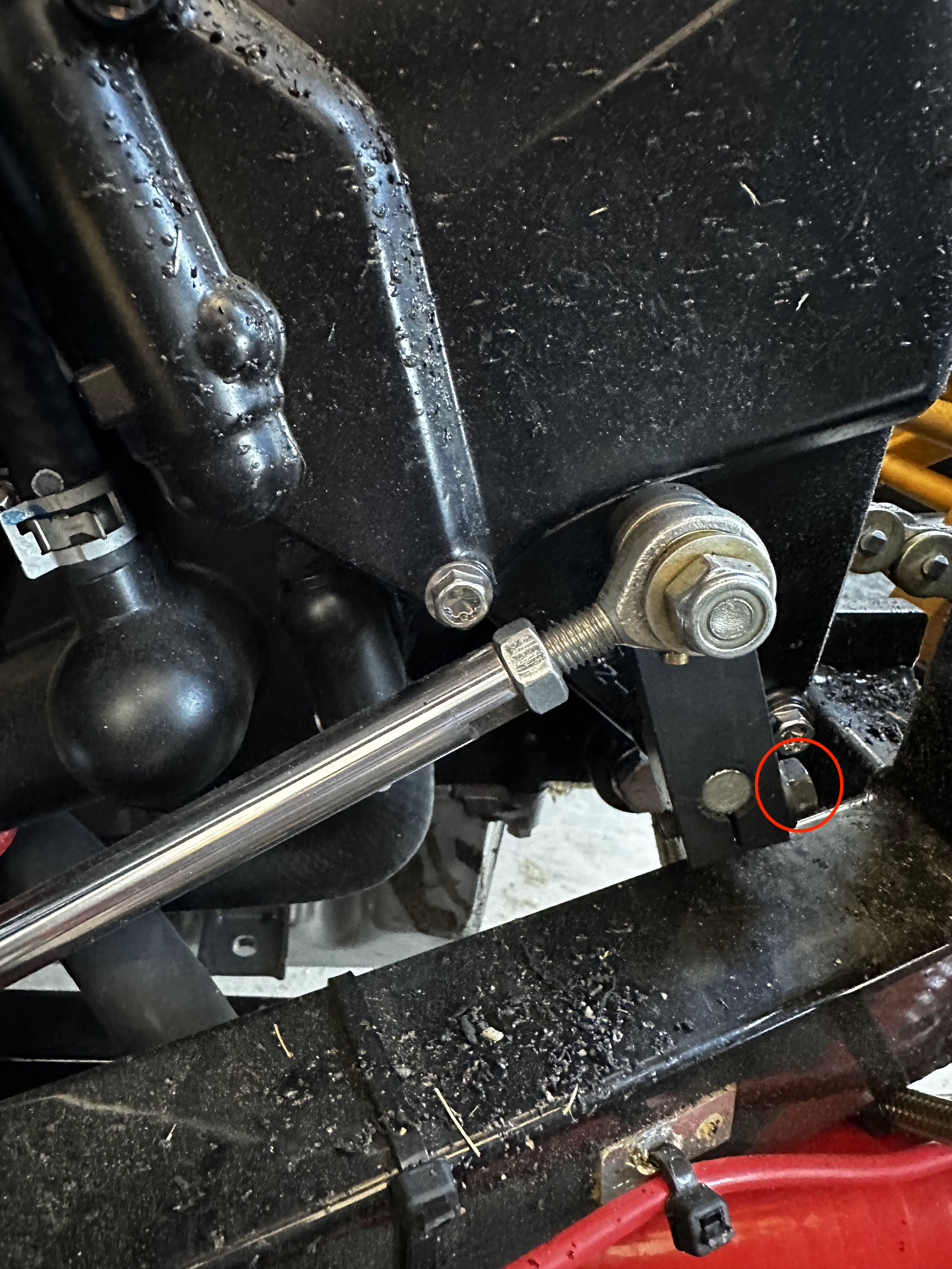
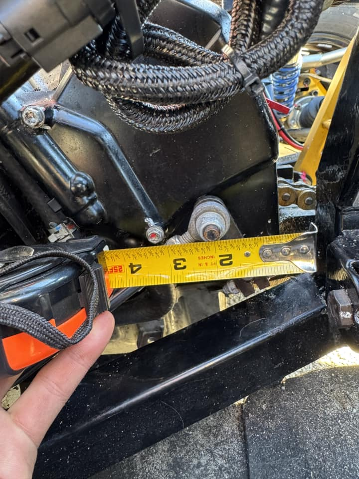
Distance between the shifter bolt (at the 2" mark) to the case bolt on the left with a red mark should be 1.25".