Main Harness
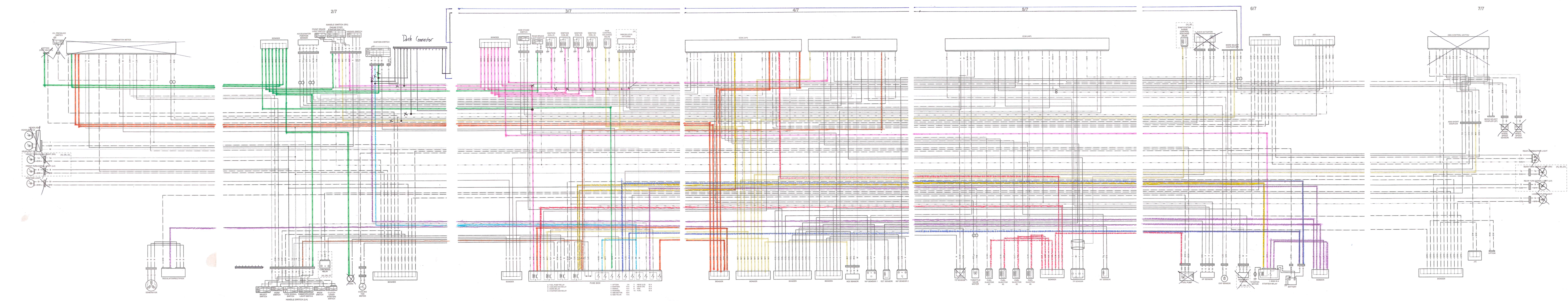
The interactive diagram below shows all active wiring in the Rush SR main harness (Gen2 drive-by-wire). Click any wire for details, or use the circuit toggles to isolate individual systems. Click “Wire Reference Table” on the dash panel for a complete wire list.
Open the main-harness-wiring-diagram diagram in a new tab
Power Distribution
Section titled “Power Distribution”Wire colors use the Suzuki convention: first letter is the base color, after the slash is the stripe. For example, R/W means a red wire with white stripes.
The main 30A fuse supplies power via a red (R) wire to the dash panel On/Off switch. From there, power is distributed through two main circuits:
- W/Y (Ignition circuit) — powers the ECU and feeds the Run switch. The Run switch outputs W/R wires to ignition coils, starter button, and fuel switch.
- W/G (Signal circuit) — powers the shift harness, AiM data logger, brake light relay, and other auxiliary systems.
The fuel switch controls the fuel pump relay. When energized, the relay outputs R/W power to the fuel pump and all four injectors. The ECU controls each injector and coil individually via ground-side switching.
Reference Diagrams
Section titled “Reference Diagrams”📥 Download: main harness wiring diagram.png Original annotated Suzuki schematic showing removed OEM components (crossed out) and Rush SR modifications.