
Shift Debugging
Troubleshooting steps for techs and crew diagnosing shift-system issues. For pin-level electrical reference (voltages, pull-ups, fail-safes), see Shift Harness and GCU. For firmware, settings, and the serial console, see Gear Control Unit (GCU). Have the GCU Gen 3? Its flash logging, live telemetry, and flashing workflow are covered separately in GCU Gen 3 — the pneumatic and mechanical sections below still apply to every car.
The page is organized by symptom. Pick the closest match from the index below and jump in — each branch ends at either a fix or a deeper sub-test.
Where to Start
Section titled “Where to Start”Shifts
- Both paddles dead and compressor won’t run → Nothing Works: No Shifts, No Compressor
- One paddle direction dead, the other works → One Paddle Direction Doesn’t Respond
- Both directions miss intermittently → Missed or Incomplete Shifts (Both Directions)
- One direction noticeably weaker (different sound, larger pressure drop) → Asymmetric Shifts: One Direction Weaker
- Missed upshifts or downshifts but not both, fails to fully engage one direction → Shift Linkage Mechanical Checks
- Audible binding during shift, weak/missed shifts that bench-test fine pneumatically → Shift Arm
- Can’t find neutral with the engine running → Can’t Find Neutral with the Engine Running
- Erratic shifting with no clear electrical or pneumatic pattern → GCU Water Intrusion
Compressor
- Runs continuously, can’t reach 90 psi → Compressor runs continuously
- Never runs at all → Compressor never runs
- Short-cycles rapidly → Compressor short-cycles
- Compressor fuse blows immediately or after a short run → Compressor never runs (relay diode, water in compressor head)
DBW cars (limp mode, no blip / no cut)
- Throttle capped with no fault codes, engine still pulls to redline → Speed Emulator
- Throttle capped and the engine stops at ~6,000 RPM in gear → Gear Position Signal
- No blip on downshift, limp mode active → Clutch Switch
- Paddles register on LEDs but no throttle blip or cut → Gearshift Sensor Mimic
Gen1 cable throttle
- No blip on downshift, cable car → Blip Cylinder Air Supply
Intermittent / power
- GCU shifts fine for a while, then dies; full car restart recovers it → Nothing Works step 3 (power-supply cap solder joints)
- No LEDs at all, Flasher can’t open the USB serial port → Nothing Works step 5 (Mega 2560 swap)
FALLBACK: Using safe default timingin the serial log → Pressure Sensor Fail-safe
Triage / bench tests
- Bisect “GCU/paddle/wiring vs. pneumatic/mechanical” in one test → Manual Pneumatic Shift Test
Reference
- LED Reference · GCU Board Reference · Reading the Serial Console
- Shift Harness and GCU (pin-level electrical) · GCU (flashing, console access, GCU Gen 3 + Legacy)
LED Reference
Section titled “LED Reference”The GCU has three diagnostic LEDs on the board plus the onboard heartbeat LED. Their meaning depends on state:
| LED | Idle (no shift in progress) | During a shift |
|---|---|---|
| Red | Off | Solid during downshift attempt |
| Yellow | Flashes ~2 Hz while compressor running | Solid during neutral attempt |
| Green | Off | Solid during upshift attempt |
| Heartbeat (D13) | Pulses continuously | Pulses continuously |
On firmware 3.0.5 and later, red → yellow → green flash in sequence at boot (~100 ms each) as a power-on self-test.
During a neutral attempt, the yellow LED lights solid together with the direction LED (green for NT+up, red for NT+down), so yellow-plus-green means “neutral upshift attempt.”
If the heartbeat LED is frozen, the firmware has hung. A cold power cycle is always the first step before chasing electrical faults.
In the rest of this page, Gen1 means KLine / throttle-cable cars and Gen2 means CAN / drive-by-wire cars (see the GCU section). A Gen2 GCU will run in a Gen1 car well enough to debug paddles and compressor behavior, but it won’t drive the Gen1 throttle cut or blip — treat any cross-generation substitution as a paddock-only diagnostic, not a track-ready swap.
GCU Board Reference
Section titled “GCU Board Reference”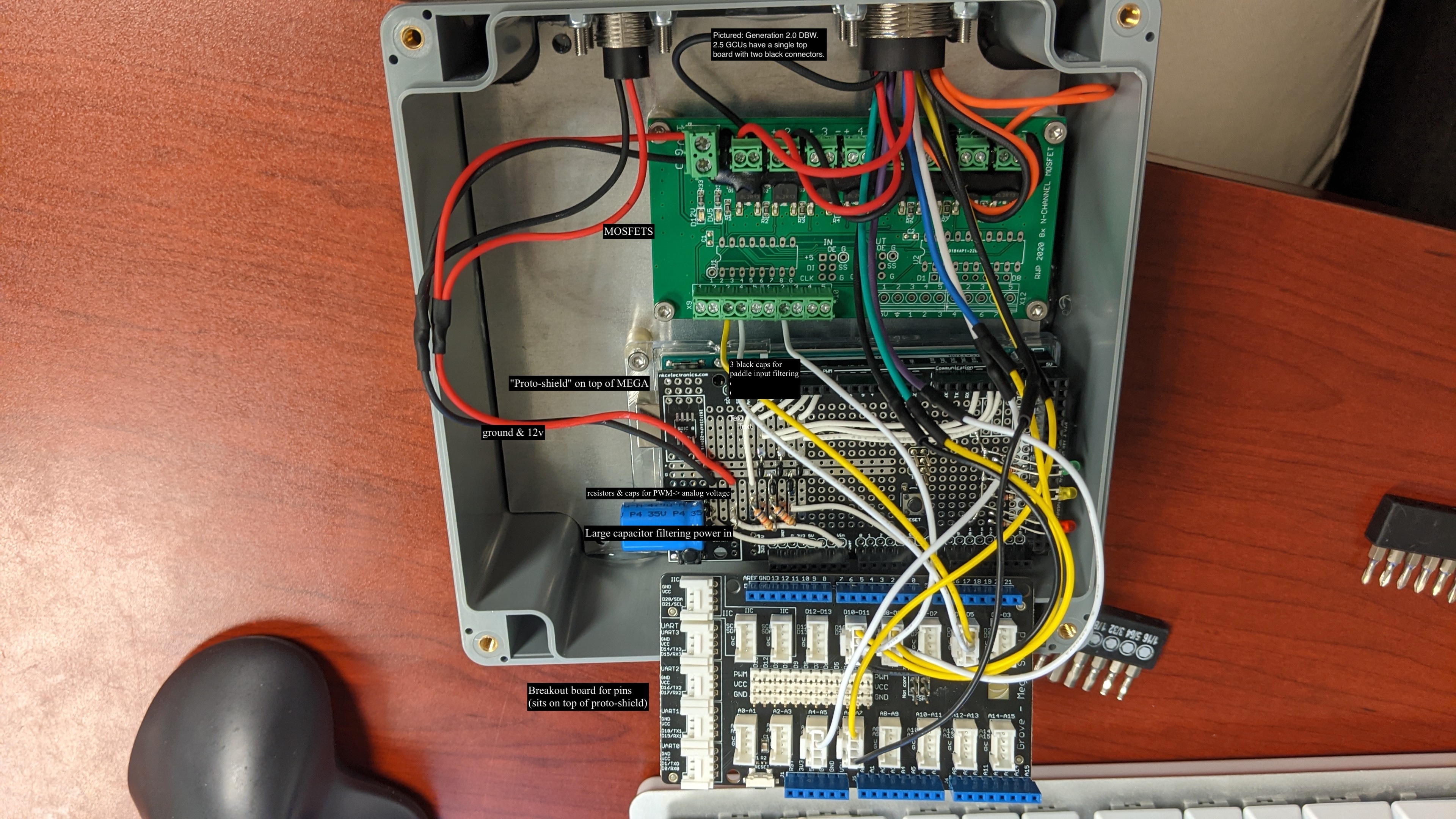
GCU 2.0 DBW board, annotated. GCU 2.5 units have a single top board with two black connectors; component positions otherwise match.
Quick map of what lives where on a GCU 2.0 DBW unit (Gen2, pictured):
- Top green board — MOSFETs. Actuator drivers; the terminals along the bottom of this board carry valve and compressor relay signals.
- Middle board — Arduino Mega 2560 with the intermediate board (also called the proto-shield) mounted on top. The intermediate board carries:
- Three black paddle-input filter capacitors (up, down, neutral) between pins 9/10/8 on the input side and pins 19/18/20-or-3 on the logic side.
- A large blue electrolytic capacitor (labeled P4 35V) filtering the 12 V power input. This is the “power-supply cap” referenced throughout the troubleshooting sections below.
- Resistors and smaller caps forming the PWM → analog voltage network for the gearshift-sensor mimic (Gen2 only; unused on Gen1).
- Bottom board — pin breakout that sits on top of the proto-shield and brings the Mega’s digital and analog pins out to labeled connectors.
Manual Pneumatic Shift Test
Section titled “Manual Pneumatic Shift Test”Bench-bypass procedure to bisect “GCU / paddle / wiring” vs. “pneumatic / mechanical” in a single test. Bypasses the GCU entirely and exercises the air path, cylinder, and linkage end-to-end.
- Confirm the air system is at full operating pressure.
- Position yourself clear of the driveline. Car on stands or wheels chocked.
- At the valve block, manually move the pneumatic shift arm forward and observe the upshift action.
- Return the arm and move it backward to observe the downshift action.
- Compare the two directions for symmetry.
Outcomes:
- Clean shift in both directions → pneumatic side is healthy. Fault sits in GCU, paddle, or wiring — proceed to the electrical sections.
- Asymmetric movement → shifter cylinder alignment or actuator rod length. See Shift Linkage Mechanical Checks.
- One or both directions fail manually → pneumatic side (valve block, air supply, leaks). See Asymmetric Shifts or Compressor Issues.
Nothing Works: No Shifts, No Compressor
Section titled “Nothing Works: No Shifts, No Compressor”Both paddles dead and the compressor won’t kick on even with air demand. The fault is upstream of the per-direction hardware. Bisect in this order:
- Drain the air tank and watch the compressor. The GCU commands the compressor on below 70 psi via the relay on pin 11. An empty tank should trigger the compressor within a second or two. If it doesn’t, the GCU isn’t making the relay call.
- Check the heartbeat LED. No pulse = firmware not running. Signal fuse, brownout, or a board-level failure — check the signal-fuse feed first (see Shift Harness and GCU).
- Suspect the GCU power-supply electrolytic capacitor (the large blue cap labeled P4 35V on the intermediate board; see the board reference). A failed power-supply cap produces exactly this pattern: no shifts, compressor won’t run even with an empty tank. The rails sag under any load, so every subsystem misbehaves simultaneously. Visual check for bulging, leaking, or discolored electrolytic caps; replace if suspect. This is the most common cause once the fuse and heartbeat LED are ruled out. A related failure on the three-board Gen1 / Gen2.0 stack is a loose solder joint at the same cap — that presents as a GCU that shifts cleanly for a while, then drops out completely and requires a full car power cycle to recover. Reflow the joints if you see that intermittent pattern.
- Pressure sensor stuck-high fail-safe. If the sensor wire is open or shorted to 5 V, the GCU reads pressure as high and keeps the compressor off on purpose (safe failure mode). See Pressure Sensor Fail-safe below — the drain-tank test already rules this in or out, because a stuck-high sensor means the compressor won’t come on even with the tank drained.
- No LEDs at all and the Flasher can’t open the USB serial port. The Mega 2560 itself is dead; the surrounding boards can’t be the cause if the Mega doesn’t enumerate over USB. The Mega is interchangeable between Gen1 and Gen2 GCUs, and a stock Arduino or Elegoo Mega 2560 clone (cheaper, fully compatible, easy to source on Amazon) drops in directly. Lift the top boards off, unscrew the Mega from the chassis, fit the new board, and reinstall the top boards.
GCU Water Intrusion
Section titled “GCU Water Intrusion”Erratic shifting with no clear electrical or pneumatic pattern often turns out to be water in the GCU housing. Corrosion across the boards produces intermittent failures that mimic every other symptom on this page.
The daily checklist calls for inspecting the GCU and compressor for water at every event and draining if needed. Cars that miss the daily check accumulate moisture over a weekend.
- Confirm the daily water check was performed for the affected session. If it wasn’t, that’s the first thing to fix going forward.
- Remove the GCU from the car following ESD precautions.
- Open the housing and inspect for visible moisture, corrosion, mineral residue, or water staining on the boards.
- Inspect sealing surfaces, gaskets, and any vent provisions for blockage or damage.
- Document any contamination before drying or cleaning — warranty and repair vendors need to see the original state.
Dry the unit thoroughly, replace damaged components, restore sealing integrity, and address the source of water entry. If corrosion is widespread, send out for repair or replace.
Can’t Find Neutral with the Engine Running
Section titled “Can’t Find Neutral with the Engine Running”If you can get into neutral with the engine off but not while the engine is running, the issue is almost always clutch-related rather than a GCU fault. A neutral shift fires a short half-length pulse to the gearbox (25 ms up-to-neutral, 28 ms down-to-neutral) and, unlike a regular shift, applies no throttle cut and no blip. If the clutch isn’t fully disengaged, the dogs stay loaded and can’t slide through the half-position.
Two things to check:
- Push the clutch pedal all the way to the floor when attempting to reach neutral. Any partial release keeps enough drive on the gearbox to prevent neutral engagement.
- Adjust your clutch cable to pull the clutch higher. If the cable is too loose, even a fully-depressed pedal won’t fully disengage the clutch. See Adjusting Throttle & Clutch Cable.
Also confirm input technique: the GCU fires a neutral shift only when the neutral paddle is held while you pull the upshift or downshift paddle. Tapping neutral by itself does nothing. The neutral input is polled (not interrupt-driven), so a momentary tap that’s simultaneous with a direction paddle can also miss — press and hold neutral first, then pull the direction paddle.
Car Won’t Start — Dash Shows N but Engine Won’t Crank
Section titled “Car Won’t Start — Dash Shows N but Engine Won’t Crank”A common variant: the dash reads N but the starter refuses to engage. The gear-position sensor is reporting neutral while the gearbox is still partially in 1st or 2nd (dogs not fully cleared). The starter interlock sees “not neutral” and inhibits cranking.
To free it:
- Wiggle the car to unload the gearbox. Even an inch of roll usually lets the dogs settle into the neutral detent. Easier with a friend pushing while you watch the dash.
- Push the clutch and tap the upshift or downshift paddle to settle the position, then back to neutral.
- Check the gear-position sensor wiring if the dash never updates regardless of car motion — see Shift Harness and GCU.
One Paddle Direction Doesn’t Respond
Section titled “One Paddle Direction Doesn’t Respond”When only one direction is dead and the other works normally, the firmware is fine (both sides share the same code path) and the fault is somewhere in the paddle → wheel → coil cable → harness → GCU chain. Work from the outside in with swaps; each swap isolates a different layer:
- Swap the up and down signal wires at the coil cable or the GCU-side connector. If the fault follows the wire to the other direction, the problem is in that wire / pin. If the fault stays on the original direction, the problem is upstream (switch, wheel-side wiring) or downstream (GCU itself).
- Ground the paddle pin directly at the GCU connector. Jumpering pin 18 (up) or 19 (down) to ground simulates a paddle press. If this produces a shift, everything from the GCU inward is fine — the fault is in the switch, wheel, or coil cable.
- Bypass the filter capacitor (up/down only). Up and down paddle signals pass through filter caps on the intermediate board — pin 10 into 18 (up), pin 9 into 19 (down). Jumpering the input pin directly to the logic pin (10→18 or 9→19) bypasses the cap. If the direction comes back, the cap is the culprit. This test is not documented for the neutral line; see Shift Harness and GCU for the reference procedure.
- Swap the entire wheel and coil cable. If a spare known-good wheel is on hand, this isolates everything from the paddle down to the GCU’s harness-side connector in a single test. Often the fastest way to confirm a wheel-side fault.
Filter Capacitor Failure Modes
Section titled “Filter Capacitor Failure Modes”The three black caps on the intermediate board (see the board reference) sit between paddle input (pins 8, 9, 10) and logic input (pins 3-or-20, 19, 18) and reject transient noise. The up/down bypass procedure above is the fastest test; failure signatures are:
- Open cap: logic pin sees unfiltered noise. Spurious shifts or missed presses, often worse on rough tracks where vibration-induced chatter gets through.
- Shorted cap: logic pin stuck near 0 V. GCU sees a continuous paddle press; the first shift fires, then further presses are suppressed until the internal state resets. Feels like “one shift then nothing.”
- Leaky / degraded cap: slow charge/discharge. Presses register with variable delay or get dropped.
The bypass test (step 3 above) is the fastest confirmation.
Paddle Switch Voltage Test
Section titled “Paddle Switch Voltage Test”Where the ground-the-pin test (step 2 above) confirms the GCU side, the voltage test confirms what the GCU is actually seeing from the switch. Useful when you suspect a stuck-closed switch or a short to ground in the wheel-side wiring.
The paddle switches are configured INPUT_PULLUP: the GCU holds each pin HIGH at ~5 V, and the switch pulls the pin LOW to 0 V when pressed.
Probe at the GCU connector with the ignition on:
- Pin 18 = upshift
- Pin 19 = downshift
- Pin 3 (DBW / Gen2) or pin 20 (KLine / Gen1) = neutral
- Pin 2 of the main harness connector = ground reference
Expected: ~5 V unpressed, ~0 V pressed. Reading interpretations:
- 0 V at all times — switch stuck closed, or short to ground in the wiring. Disconnect the wheel-side coil cable and re-probe to bisect.
- 5 V at all times even when pressed — switch isn’t making contact (open circuit) or a bad pin in the coil cable connection.
Paddle Magnets
Section titled “Paddle Magnets”If the symptom is on one paddle only and the wheel / switch / coil cable tests good, check the magnets. Ferrous debris on the magnet face can prevent full travel of the paddle, and magnets can crack or work loose from their seats.
- Confirm the symptom is on one paddle only. Symptoms on both paddles point to the steering wheel cable or upstream, not the magnets.
- Inspect magnet faces for ferrous debris, contamination, cracks, or chips.
- Verify the momentary switches are being depressed when the paddle moves through full travel.
Clean debris off the face. Replace any magnet that’s cracked, weakened, or no longer seated correctly.
Asymmetric Shifts: One Direction Weaker
Section titled “Asymmetric Shifts: One Direction Weaker”One direction misses shifts noticeably more often than the other — and, importantly, sounds different from the cockpit. The fault is in the valve block or the air path feeding one valve, not in the electronics. Firmware runs both directions through identical code.
Diagnostic steps:
- Listen. A healthy shift is a sharp crack from the valve block; a weak one sounds muffled or extended. A persistent hiss after the shift indicates that valve is venting past its seat.
- Compare the pressure drop per shift. A normal 125 ms shift at ~80 psi consumes roughly 4 psi of tank air (about 3 psi at high-pressure / 90 ms shifts on firmware 3.0.6+). Read the drop off the AiM dash or analog gauge. Much larger drop on one direction = that valve is venting too much; much smaller drop = that valve isn’t fully opening.
- Inspect the valve block Amphenol connector before pulling the block — see the next section.
- Replace the valve block if the Amphenol is clean and the asymmetry persists. The valve block is a single unit with three solenoid valves (upshift, downshift, throttle blip — the blip valve is unused on drive-by-wire cars), air in, two or three outputs, and shared electronics.
Inspecting the Valve Block Amphenol Connector
Section titled “Inspecting the Valve Block Amphenol Connector”Before pulling a valve block, check the small Amphenol connector on the block itself. We’ve seen a pin sit unseated inside the connector housing — the shift was intermittent, but nothing on the wiring side looked wrong. Procedure:
- Disconnect the Amphenol connector from the side of the valve block.
- Visually inspect the pins on the block-side half of the connector. An unseated pin sits proud of its housing instead of flush with its neighbors.
- If a pin is proud, push it fully home with a small blunt tool until it seats flush with the others.
- Reconnect and test. If shifts return, done.
If all pins are seated correctly and the block still misbehaves per the asymmetric-shifts symptoms, the valve itself is the likely cause. The shift valve is on a four-event service interval — an overdue valve service can masquerade as a mechanical fault.
Shift Linkage Mechanical Checks
Section titled “Shift Linkage Mechanical Checks”When electrical and pneumatic checks come back clean — or the Manual Pneumatic Shift Test flagged an asymmetry — the mechanical linkage is the next stop.
Shift Arm
Section titled “Shift Arm”Symptoms: audible binding during shift, missed shifts in either direction, weak shifts that bench-test fine pneumatically.
Probable causes: shift arm contacting the case saver, mounting hardware loose, worn splines.
- Visually inspect shift arm position and clearance to the case saver through the arm’s full range of motion.
- Confirm all mounting hardware is tight and the arm pivots freely with no detectable play.
- With the air system pressurized and the car safe to actuate, manually trigger a shift and watch the arm sweep for hesitation or contact.
- Inspect for galling, burrs, or witness marks on the arm and case saver.
Adjust clearance / shim to restore clearance, torque hardware to spec, replace worn arm or pivot components as needed.
Actuator Rod Length and Cylinder Alignment
Section titled “Actuator Rod Length and Cylinder Alignment”Symptoms: missed upshifts or missed downshifts but not both; fails to fully engage one direction.
The pneumatic shift cylinder needs equal range of motion in both directions. If the rod length is off or the cylinder is misaligned with the shift lever, the weak direction runs out of travel and the dogs don’t engage.
Rush spec: distance from the shifter bolt at the 2″ mark to the case bolt on the left (red mark) = 1.25″.
- Verify the actuator rod is at the documented length specification.
- Measure shifter bolt → case bolt distance and confirm 1.25″.
- Cycle the shift mechanism manually and compare fore/aft travel for symmetry.
- Compare engagement against a known-good reference car if available.
- Check rod end joints for wear or play that could be absorbing stroke.
Loosen the cylinder alignment bolt and adjust so the cylinder swings the same distance fore and aft. The shifter bolt → case bolt distance should be 1.25″ after adjustment. Replace the rod if threads are damaged or rod ends are worn.
Missed or Incomplete Shifts (Both Directions)
Section titled “Missed or Incomplete Shifts (Both Directions)”Both directions occasionally misfire, typically under load or at low pressure. If the misfires are clearly biased to one direction, skip to the asymmetric-shifts section above instead. Likely causes in rough order:
- Low tank pressure. Firmware 3.0.6 adapts shift timing to tank pressure (90 ms above 150 psi, 125 ms in the normal 70–90 band, up to 175 ms below 30 psi). But a tank stuck well below 70 psi still produces weak shifts. Watch the yellow LED after a shift burst — if the compressor can’t catch up, you’re shifting faster than the tank can refill (~1 psi/sec in the 70–90 band). Points back to compressor sizing, an air leak, or an asymmetric valve.
- Countershift disabled or mistuned. Countershift (a brief reverse pulse after each shift to seat the dog ring) is on by default in both directions as of 3.0.4, and configurable per direction in 3.1.0. If countershift was turned off experimentally, turn it back on before chasing other causes. Contact Rush Auto Works before changing countershift settings.
- Shift cylinder / gearbox. If air is healthy, countershift is on, and asymmetric-shift checks come back clean, the mechanical side is next — worn cylinder seals, stuck piston, or a shift fork issue. Inspection requires pulling the shifter.
Compressor Issues
Section titled “Compressor Issues”The yellow LED flashes ~2 Hz while the compressor is running (firmware 3.0.5+). Hysteresis is hard-coded: compressor on below 70 psi, off above 90 psi.
Compressor runs continuously
Section titled “Compressor runs continuously”The tank can’t reach 90 psi. Quick math for context: the Kleinn 6270C compressor fills at about 1 psi/sec in the 70–90 band, and a single 125 ms shift at 80 psi consumes roughly 4 psi, so recovery after one shift takes about 4 seconds. If the compressor runs indefinitely with no shifts happening, look for leaks first — spray soapy water on fittings, the valve block seams, hose crimps, and cylinder seals under pressure and watch for bubbles.
If the air system is tight and the compressor still won’t cycle off, a MOSFET stuck open on the GCU can hold the compressor relay closed regardless of pressure or GCU command. Track-side workaround: redirect compressor control from MOSFET 5 to MOSFET 6 — move pin 11 off the board to MOSFET 6 control, and move the orange and black wires on MOSFET 5 output across to MOSFET 6 output. The rest of the GCU stays functional until the board can be repaired.
Compressor never runs
Section titled “Compressor never runs”Yellow LED never flashes: either the GCU thinks pressure is already above 90 psi (stuck-high sensor, see Pressure Sensor Fail-safe), the compressor circuit is dead, or the GCU itself isn’t running (see Nothing Works: No Shifts, No Compressor above). Drain the tank to force the compressor demand — that one test separates sensor vs. board vs. compressor. If the yellow LED is flashing but the compressor stays silent the GCU is making the call, and the fault sits on the power side. Work cheapest to most involved:
- Fuses. Check the compressor / ABS fuse before assuming a board fault.
- Compressor supply harness. The harness feeding power to the compressor can work loose or go intermittent — reseat the connector and check for vibration damage at the crimps.
- Black 4-wire relay. We’ve seen this relay fail. The four terminals sit at N, S, E, W: N = red, E = red/black, S = red, W = black/black. N and S are interchangeable. See the shift harness wiring diagram for the full circuit.
Pin-level test procedure
Section titled “Pin-level test procedure”The compressor circuit is always hot via the ABS fuse, regardless of ignition switch position — so the compressor will run any time the relay closes (you can’t kill a stuck compressor by turning off the dash; pull the fuse). Power path: ABS fuse → 12 V → main-harness pin 5 → relay pin 30.
Auto relay pinout: pins 85/86 = coil, pins 30/87 = contacts.
Compressor 2-circuit receptacle: pin 1 (red #21) = 12 V hot, pin 2 (black #22) = ground.
Direct tests (work outward from the compressor):
- Compressor direct: Disconnect the 2-circuit receptacle and apply 12 V to pin 1, ground to pin 2. If it doesn’t run, replace the compressor.
- Relay direct: Disconnect from the harness, apply 12 V to pin 85 and ground to pin 86. Listen for the click and confirm continuity 30→87. If not, replace the relay.
- Relay diode: Bench test for proper directional conduction. A failed diode produces the “compressor fuse blows immediately or after a short run” pattern.
- GCU relay output: With the relay connected and tank below 70 psi, check for voltage at relay pin 85 against ground. The GCU’s MOSFET should pull pin 86 to ground when commanding the compressor on. No click with a known-good relay = suspect the GCU output stage.
The compressor is on a four-event replacement interval. Compressor fuse blowing is also produced by water intrusion in the compressor head itself — inspect the head if the fuse blows on a relay that bench-tests clean.
Compressor short-cycles
Section titled “Compressor short-cycles”Rapid on/off typically means a slow leak drops pressure below 70 psi shortly after each fill, or the pressure sensor is noisy near the thresholds.
Quantifying a leak: pressure decay test
Section titled “Quantifying a leak: pressure decay test”If the compressor cycles more frequently than baseline but no audible or soapy leak shows up, time the pressure decay against a known-good baseline car:
- Confirm the air tank has been drained per the weekend interval.
- With the car powered off, pull the purge valve to drain the tank completely. Then refill.
- Pressurize to ~90 psi and turn the car off.
- Time how long it takes to drop a fixed amount (e.g. 90 → 80 psi). Compare against a baseline car.
- Soap-test every fitting, line, solenoid, and tank connection while pressurized — including under flow (during a manual shift trigger) to catch leaks that only open up during a shift event.
- Inspect air lines for cracks, chafing, or kinks that indicate partial leaks or impending failures.
Finding an air leak
Section titled “Finding an air leak”If the compressor is working often even when you’re not shifting, the system is leaking somewhere. Standard approach:
- Pressurize the system, then turn the car off and listen — a loud leak is audible.
- Spray soapy water on every fitting, valve block seam, hose crimp, cylinder seal, and Schrader valve. Bubbles betray the leak.
- Purge the air tank a few times (car off!) by pulling the purge valve — it has a small pull that looks like a key ring. Purging clears moisture or contamination that can hold valve seats open.
Limp Mode, No Blip, No Cut (DBW cars)
Section titled “Limp Mode, No Blip, No Cut (DBW cars)”Several independent subsystems on drive-by-wire cars produce overlapping symptoms — limp mode, no throttle blip on downshift, no ignition cut on upshift. Start by reading which limp mode you are in, then work in this order: Speed Emulator → Gear Position Signal → Clutch Switch → Gearshift Sensor Mimic. The LED triage tells you whether the GCU is even commanding the shift; if LEDs are clean, the fault is downstream in the ECU signal path.
OBD connector convention: Red OBD connector = Gen2 DBW, White OBD connector = Gen1 cable throttle. Use the red connector for everything in this section.
Two Known Limp Modes (DBW cars)
Section titled “Two Known Limp Modes (DBW cars)”The Suzuki ECU limits the car in two ways we have identified. Both cap throttle, so both feel slow. The tachometer tells you which one you are in before you connect anything.
| What the car does | Cause | Go to |
|---|---|---|
| Throttle capped (around 40 %), but the engine still revs all the way to redline. The car feels slow everywhere and pulls normally at the top. | The ECU is not getting a wheel-speed signal it believes. | Speed Emulator |
| Throttle capped and the engine stops at about 6,000 RPM in gear. Quickshift sometimes drops out with it, so shifts go long, inconsistent, or fail outright. | The ECU is not getting a gear-position signal it believes. | Gear Position Signal |
The 40 % figure is an estimate from cars seen in limp mode, not a measured ECU constant. Treat it as “clearly capped, nowhere near full travel”.
Both apply to any drive-by-wire car, Gen2 and Gen 3 alike, because the limiting happens inside the donor Suzuki ECU. What differs is where the signal comes from: on a Gen 3 car the GCU generates wheel speed and reads its own gear sensor, so its logs will tell you which signal went away.
Speed Emulator (Gen2 DBW)
Section titled “Speed Emulator (Gen2 DBW)”The ECU expects a constant speed signal to keep throttle authority above limp mode. A failed Speed Emulator caps throttle at around 40 % with no fault codes — the classic limp-mode signature without OBD evidence. Revs are not limited: the engine still reaches redline, which is what separates this from a gear-position fault.
- Connect OBD-II via the Red connector. If throttle is capped near 40 %, suspect the emulator first. (Codes take time to trigger; shift issues may appear before codes are set.)
- Verify a speed value of approximately 25 mph is being reported through OBD.
- With the car stationary in neutral, rev the engine. A rev limiter at ~6000 RPM in neutral confirms the emulator is sending a stationary speed signal.
- If the engine revs past 6000 RPM in neutral, the emulator isn’t communicating.
Resolution: replace the speed emulator.
Gear Position Signal (DBW cars)
Section titled “Gear Position Signal (DBW cars)”When the ECU cannot read which gear the car is in, it caps throttle and holds the engine to about 6,000 RPM in gear. That is the limit a bike applies in neutral, and an ECU with no usable gear reading applies it everywhere.
The expensive part is the second symptom. Suzuki’s QuickShift logic needs a valid gear before it will blip or cut, so it switches itself off. Shifts then run on air pressure alone against a loaded gearbox: long, inconsistent, and some fail outright.
Driving it in. You can do the ECU’s job with your right foot until you are back in the paddock. Lift to unload the box for an upshift, blip for a downshift, and pull the paddle at the same moment. Shifts that would not go through on their own usually will.
- Watch the gear number on the AiM dash through a few shifts. A reading that sticks, blanks, or disagrees with the gear you are in confirms the fault without any tools.
- On a Gen 3 car, check the status LED. A fast amber flash means no gear data at all — shifts are running on a timer and the safety gates are off. See Status LED Quick Reference.
- Still on Gen 3, read the heartbeat line in the flasher console.
src=GPis healthy andsrc=FALLmeans the gear source is gone.g=(the GCU’s own sensor) andcg=(the ECU’s gear over CAN) should agree, and255in either means unknown. - Capture a log and look for
CAN_TIMEOUT_GEAR,GEAR_MISMATCH, andSHIFT_BLOCK_INVALID_CAN. A mismatch is harmless for about 100 ms after a shift and meaningful when it persists. See Capturing a log. - Check the neutral switch hasn’t been broken off — it feeds the same picture and is easy to knock loose.
Resolution: repair the gear-position sensor or its wiring. On a Gen 3 car the logs tell you whether the sensor itself went away or the ECU stopped sending gear over CAN, and those are different repairs.
Clutch Switch (Gen2 DBW)
Section titled “Clutch Switch (Gen2 DBW)”A failed or misadjusted clutch switch on a Gen2 DBW car produces limp mode with no blip on downshift.
- Check the AiM dash or data log to confirm the clutch switch state through a session. The AiM channel should toggle cleanly between pressed and released.
- Cross-check via OBD scanner.
- Manually actuate the clutch pedal while watching the state change on the dash or scanner.
- Verify the neutral switch hasn’t been broken off — it presents similar symptoms.
Resolution: adjust the activation point; replace the switch if it won’t actuate cleanly.
To add a clutch switch (for in-gear starting) rather than diagnose one, see Clutch Switch.
Gearshift Sensor Mimic (Gen2 DBW)
Section titled “Gearshift Sensor Mimic (Gen2 DBW)”On Gen2 DBW cars the throttle blip and ignition cut are handled by the Suzuki QuickShift logic inside the ECU, not by the GCU directly. The GCU sends a PWM signal on pin 12 that emulates the bike’s gear-lever sensor — that signal is what tells the ECU to blip on downshift and cut on upshift. If the mimic path fails, you get no blip and no cut despite paddles, Speed Emulator, and shifts themselves all testing good.
This is a separate component from the Speed Emulator — don’t conflate the two.
- Confirm Gen2 DBW car. (Gen1 cable cars use direct GCU outputs on pins 6 (blip) and 7 (ignition coil interrupt) instead.)
- Use the LED Reference to confirm the GCU is registering paddle input.
- Run the Speed Emulator check above and confirm it tests good.
- With the engine running and the car on stands or wheels chocked, command an upshift and listen for throttle cut. Command a downshift and listen for the blip. If neither response occurs, the mimic path is suspect.
- Watch the serial console for
Writing X.XXV to DAC pin(orWriting X.XXV to GSS pin) during shift commands. Absence of this line during a shift = GCU isn’t driving the mimic. - At the GCU 19-circuit plug, verify continuity from pin 12 to the ECU input.
If continuity is good but the GCU isn’t driving the output, the fault is internal to the GCU output stage — send out for repair or replace.
Blip Cylinder Air Supply (Gen1 cable throttle)
Section titled “Blip Cylinder Air Supply (Gen1 cable throttle)”On Gen1 cable-throttle cars, the downshift blip is produced by an air cylinder that pulls the throttle cable open through a dedicated valve. No blip on a cable car can mean a loose or stretched throttle cable, an over-extending throttle that trips the ECM limp-mode threshold, or a leak in the blip air supply.
OBD throttle check (use the White OBD connector for Gen1 cable cars): peak throttle position must not exceed 95 % under any condition; AiM dash setup target is 92 %. Above 95 % triggers limp mode at full throttle.
- Verify throttle cable tension and free play. Adjust as needed — see Adjusting Throttle & Clutch Cable.
- Inspect the throttle cable for fraying along its full length.
- Read peak throttle on OBD. Target 92 %, hard limit 95 %.
- Confirm the air system is at full operating pressure.
- Inspect the blip-cylinder air supply line for kinks, chafing, or visible damage. Apply soap solution to the cylinder fittings and supply line during a manual blip event to find leaks.
- Manually trigger a blip and observe the cylinder stroke through its full range of motion.
Resolution: adjust throttle cable so OBD doesn’t exceed the 92 % target. Repair or replace the air supply line. Reseal or replace the blip cylinder if internal seals are compromised.
Pressure Sensor Fail-safe
Section titled “Pressure Sensor Fail-safe”The GCU validates every pressure reading before using it for timing. Readings rejected: NaN, infinite, negative, or outside roughly −10 to 250 psi. Invalid readings cause dynamic timing to be bypassed; the GCU falls back to the fixed 125 ms shift delay used before 3.0.6. Shifts still work; they just don’t adapt to pressure. Repeated FALLBACK: Using safe default timing due to pressure sensor failure lines in the serial log point at the A6 sensor wiring.
A sensor that reads stuck-high pulls the compressor off (safe failure — you can’t overpressure the system). A sensor stuck low would drive the compressor continuously; the pull-up on A6 prevents this on a clean disconnect, but a pinched wire that shorts to ground can still produce that symptom.
Pressure sender details and voltage test
Section titled “Pressure sender details and voltage test”The sender is a 10-bit analog input on GCU pin A6, calibrated at 0.1633 psi per unit (range 0 – 1023). It lives on the pressure-sensor 4-circuit plug (Pu / Gr / LBl wires per the 51700 Rev B shift harness). A6 is configured INPUT_PULLUP, which produces the safe-failure behavior above: a disconnected sensor reads ~5 V → GCU interprets as high pressure → compressor stays off.
To test:
- Compare the GCU’s reported pressure (via the serial console
tank_psi = Nline or the GCU utility) against a mechanical reference gauge on the tank. Disagreement = sender has failed. - Voltage test at GCU pin A6 against ground. Voltage should vary proportionally with tank pressure — a full tank (~90 psi) reads higher voltage; an empty tank reads lower. A reading stuck at 0 V or 5 V regardless of pressure indicates a faulty or disconnected sensor.
- Before condemning the sender, verify the 4-circuit plug is fully seated and the Pu / Gr / LBl conductors show continuity back to GCU pin A6.
Reading the Serial Console
Section titled “Reading the Serial Console”Connect at 115200 baud via the GCU Flasher’s console (see Legacy GCU for the Legacy GCU). At boot you’ll see:
Processor is working in main loop.Firmware 3.1.0Running in CAN mode.(KLine mode on Gen1 cars.) During normal operation the GCU prints a line for every paddle press and every completed shift. Useful patterns:
upshift attempt/downshift attempt/NT upshift attempt/NT downshift attempt— the GCU detected the paddle input. If you pull a paddle and see nothing, the switch, wheel wiring, coil cable, or filter cap is at fault, not the valve block.Shift completed in X ms. Pressure: Y PSI. Shift Delay: Z ms...— a full shift ran to completion. If you see this line but no gear change, the mechanical side (valve block, cylinder, shift fork) didn’t follow through.- Periodic
tank_psi = N— sanity check on the pressure reading. Values stuck at 0 or near the sensor max (~150) indicate a wiring fault; compare to the analog gauge or AiM dash. Writing X.XXV to DAC pin(CAN cars) orWriting X.XXV to GSS pin— the GCU is driving the gearshift-sensor mimic to request blip/cut from the ECU. Absence of this line during shifts on a Gen2 car means the QuickShift request isn’t reaching the ECU.FALLBACK: Using safe default timing...— pressure sensor reading rejected as invalid; see the section above.reset state— normal housekeeping at the end of each shift.
Leave the console connected during a test drive around the paddock to capture intermittent issues in context.